
GALLOP TURBO
Turbocharger
Precision Crafted, Artisan Soul
Product Type:
VT (Wastegate Turbocharger), VF (Variable Flow Turbocharger), VG (Variable Geometry Turbocharger) series turbo assemblies, turbo cores, turbine shafts, impellers, floating bearings, overhaul kits, wastegate valves, exhaust cover plates, electronic actuators (solenoid valves), VGT variable geometry (nozzle ring).
For more information about our products, please contact us.
Product
Handmade precision, created with care
FEATURED PRODUCTS
Artisan Precision, Heartfelt Creation
")
New GT37 Turbo For Cummins ISLE 375 30 Engine 4051033 755134-5001S Turbocharger
New GTB4088 Turbo For Caterpillar CAT349 C13 Engine 440-9241 440-9239 815723-5012S 815723-5008S Turbocharger
New HE400VG Turbo For PC360LC-10 PC390LC-10 Engine 3796115 6746-81-8110 Turbocharger
New HX40W Turbo For Cummins 6BTAA Engine 4051033 3783602 3785224 755134-5001S Turbocharger
New K31 Turbo For Mercedes Benz OM501LA-E4 Engine 53319886911 53319886906 53319706911 Turbocharger
New KP39 K04 Twin Turbo For Mercedes Benz Sprinter C-Class OM651 Engine 10009880074 A6510900980 53049700086 Turbocharger
New RHE62 Turbo For 6LP Engine VC720033 119775-18010 119775-18150 E61CAD-S0033G 6T-609 Turbocharger
New S4TW Turbo For TAMD163A TAMD165A-A Eigine 315097 3825186 3802102 314756 Turbocharger
New TD025 Turbo For Ford Citroen Peugeot 1.6L Engine 49373-02003 AV6Q-6K682-BB Turbocharger
New Turbo For 3412 3412C SR4 Engine 7C-2485 7C2485 312002 194848 179576 198848 Turbocharger
")
")
")
")
")
")
")
")
")
")
new product
Where Precision Meets Artistry
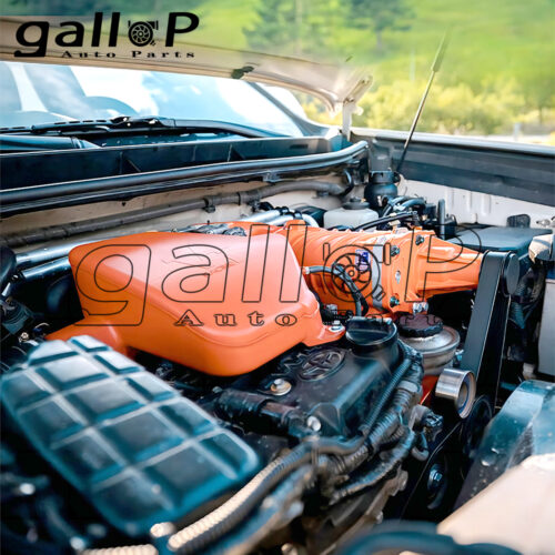
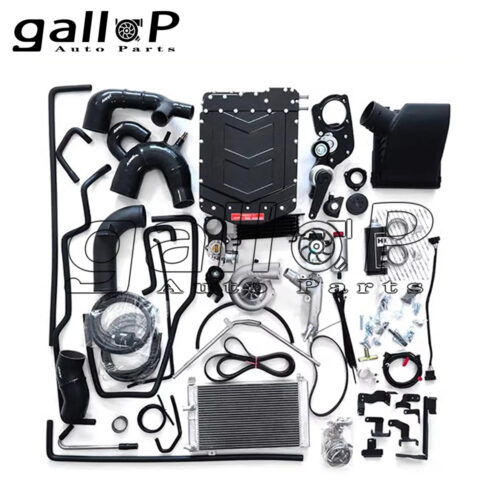
Car Conversion
Exhaust gas turbocharger
VT twin-screw, HKS centrifugal mechanical supercharger