
1.Core Structural Linkage
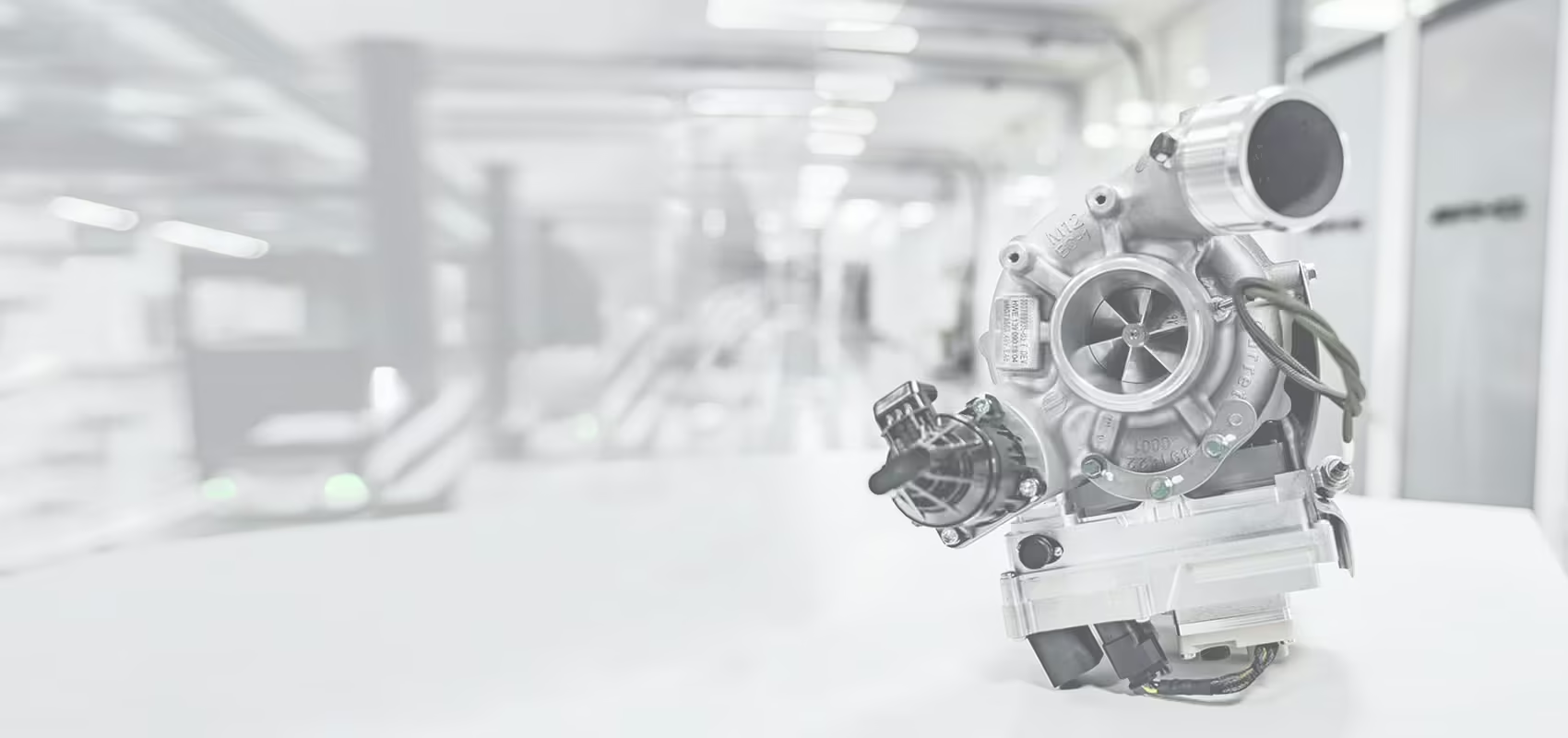
A turbocharger consists of a waste-gas turbine and a centrifugal compressor rigidly connected via a coaxial shaft, forming a high-speed rotor system that rotates between 135,000 and 200,000 RPM. The turbine housing is integrated with the engine’s exhaust manifold, while the compressor connects to the intake system.
2.Energy Conversion Process
Exhaust-Driven Phase
High-temperature exhaust gases (600–900°C) flow through the turbine housing at velocities of 20–50 m/s, driving the turbine wheel to rotate at speeds exceeding 100,000 RPM. Approximately 30% of the exhaust’s kinetic energy is converted into mechanical energy. Critical parameters include turbine blade materials (nickel-based alloys withstand 950°C, ceramic composites up to 1,050°C) and exhaust velocities reaching 70% of the speed of sound under full load.
Air Compression Phase
The coaxial compressor impeller pressurizes ambient air to 1.3–2.5 bar. After passing through an intercooler (achieving a 60–80°C temperature reduction), the cooled air’s density increases by 30%. Key performance metrics include centrifugal compressor efficiency (72–78%) and intercooler effectiveness (85–93%).
Combustion Optimization
The high-density air lowers the air-fuel ratio from 14.7:1 to 12.5:1, enabling a 22–30% increase in fuel combustion efficiency. This allows smaller turbocharged engines (e.g., 1.5T) to match the power output of larger naturally aspirated engines (e.g., 2.0L).
3.Technical Innovations
Turbo Lag Mitigation
Variable Geometry Turbine (VTG): Electronically adjustable guide vanes optimize exhaust flow across engine speeds, maintaining constant boost pressure between 1,750 and 5,000 RPM.
Electric Assist Turbocharging: 48V electric motors drive auxiliary turbines (e.g., Mercedes-Benz M256), reducing response times to 0.3 seconds.
Bearing Advancements
Floating Bearings: Utilize dual-layer oil film lubrication with 0.05–0.1mm clearances.
Ball Bearings: Reduce friction by 40% but have shorter service lives (~80,000 km).
Air Bearings: Contactless magnetic or hydrodynamic designs enable ultra-high speeds (>300,000 RPM), ideal for hydrogen fuel cell applications.
4.Lubrication & Thermal Management
Floating Bearing Lubrication
Requires 0W-40 full-synthetic oil maintained at 2.5–4.5 bar pressure. A 90-second post-cold-start idling period ensures oil temperatures exceed 60°C for optimal viscosity.
Cooling Mechanisms
Turbine Housing: Nickel-chromium-silicon alloy construction resists temperatures up to 950°C.
Compressor Wheel: Precision-machined aluminum alloy impellers minimize heat retention.
Dual-Channel Cooling: Combined oil and coolant circulation keeps bearing temperatures below 300°C.
5.Comparison of Turbocharging Types
Exhaust Turbochargers
Drive Mechanism: Exhaust gas energy
Response Time: 0.5–2 seconds
Efficiency: 75–85%
Applications: Mainstream passenger vehicles
Mechanical Superchargers
Drive Mechanism: Belt-driven by the crankshaft
Response Time: Instantaneous
Efficiency: 60–70%
Applications: High-performance sports cars
Compound Turbochargers
Drive Mechanism: Hybrid exhaust + electric drive
Response Time: 0.3 seconds
Efficiency: 85–90%
Applications: Advanced hybrid powertrains
6.Maintenance Guidelines
Cold Start Protection: Avoid aggressive acceleration until oil reaches operating temperature.
Post-Drive Cooling: Idle for 2 minutes after high-load driving to prevent oil coking in bearings.
Scheduled Maintenance: Clean compressor impellers every 30,000 km—0.1mm of carbon buildup can reduce efficiency by 15%.
Turbocharging technology exemplifies energy recovery engineering, transforming waste heat into usable power. With innovations in materials (e.g., titanium-aluminum alloys) and adaptive control systems, modern turbochargers are evolving toward zero-lag operation and full-range efficiency. For detailed operational parameters, refer to OEM technical specifications or SAE/ISO standards.